

Spitfire74
-
Posts
34 -
Joined
-
Last visited
Content Type
Forums
Blogs
Events
Downloads
Gallery
Membership & Shop
Posts posted by Spitfire74
-
-
Evening everyone,
We are looking to move house and sadly this might mean I won't have a garage/workshop for the Spitfire 😢.
I've tried to find private (I.e. not commercially licenced) workshops/sheds for sale through Google but to no avail. Does anyone have any suggestions on how to find any? Not looking to commit to anything just yet, but researching incase our move doesn't involve a workshop/garage included with the house!
Cheers in advance, Nick
-
Potentially interested. Could you post some photos?
-
Rob,
Ah ok I hadn't realised that was all it was!
Reference the 'second connection to the positive terminal', I assume this is what would be attached to the empty spade? That tape on the white wire is there because the plastic cover has worn away so just covering the bare wire under part of it.
Cheers, Nick
-
Hi Danny,
Thanks for your reply. I note what you say about no pink/white wire in the pictures, however having looked at the wiring diagram for a 1500 in the back of the Haynes Manual, I'm not certain that any of those wires are the correct colour! Are you able to advise as to where I would be able to locate the ballast resistor if present?
I'm away from the car until Friday but will check the resistance when I am back with it (I assume it is a terminal of the multimeter onto each winding screw?).
Thanks again.
-
Evening all,
So I need to replace the coil on my Spitfire (MkIV with a 1500 engine). I want to use a Sports Coil in order to upgrade from the current (possibly original but now buggered!) coil. I have found this one (https://www.moss-europe.co.uk/shop-by-model/triumph/spitfire/electrical-system/ignition-system/sports-coil.html) on Moss Europe, but am unsure whether I need a ballasted or non ballasted coil?
Is anyone able to advise?
Pics of my current coil below;
Thanks in advance,
Nick

-
Quoted from RobPearce-
Having looked at the page again, I see that they do include some rubber lifting pads, so the "speed hump" approach isn't what the manufacturer intends.
Ah yep just seen that, that seems to be the solution to the problem of lifting on the sills as I guess they would just sit under the appropriate jacking points like a normal trolley jack would! I was worried about the idea of just driving on like the sped hump approach you mention, couldn't see how that would not be bad for the car!
Also, would love a 2 post lift but sadly it won't fit in under the rafters of my garage. This would and would still allow me to raise the car so the wheels are approximately shoulder height and give me much better access under vehicles than jacking onto axle stands.
Quoted from Pete Arnold-
But I hope you've spotted that the website states "Out of stock"
Ah damn, it wasn't when I posted this haha!
Quoted from AndyTR-
I think it depends what type of scissor lift you're talking about. The drive-on ones do restrict a lot of access.
I've had one of these for years https://strongmanlifts.co.uk/product/tamar/ and it gets lots of use. A 2 or 4 post lift would be great but I've yet to find one that has short enough posts to go in a domestic garage.
A few years ago, I recessed the Tamar into the garage floor and that means it's there when I want it and not in the way at all when I don't. Previously, I needed some small ramps alongside the lift to get the Spitty over it. But I think the "classic" ones are a bit lower now.
Arms with pads mean I can lift the car at exactly the points I want. I've used it on Spit, Vitesse TR and Jags (and even an Aston once...).
It's my favourite tool!
Andy, surely that kind restricts access underneath even more as you have the gubbins of the mechanism in the middle under the car!?
-
Quoted from RobPearce-
I wouldn't use that type of lift on any car, but certainly not a Spitfire. However, you can make it acceptable by adding some "pads". Get several blocks of metal (or hard wood) and stick a heavy rubber pad on one face of each. Then place those blocks, rubber pad up, on the platform under the lifting points the car is designed with. In the case of the Spitfire, that's the chassis - corners at the back and the suspension attachment points at the front.
Hi Rob, what would be your reason for not using? Curious as having done research into lifts, this style seem very popular and indeed recommended!
Your suggestion of making lifting pads makes a lot of sense. Thank you!
-
Colin, what do you mean by adjustable pads? All the ones I've seen have got fixed widths and the lifting platforms don't move sideways (see link above) so you wouldn't be able to make it less wide to fit inside the sills.
-
Evening all,
I'm thinking about installing a scissor lift (https://www.automotechservices.co.uk/products/as-7532b-3-2t-mid-rise-scissor-lift/) in my garage for maintenance of my vehicles, including the Spitfire MkIV. My concern though is that the lift would damage the sills of the Spitfire. Has anyone got any experience with these with Spitfires?
Thanks, Nick
-
Ah right glad to know I have the correct gearbox for the engine then. Is that an issue having the wrong diff?
On the inside of the bonnet there are two distinct lumps at the right distance for the badge pins but I can't see any evidence on the rear wings.
-
Hi Rob
1.) Reverse is on the RHS of the gearstick and I have Overdrive
2.) Commission number on the bulkhead (RHS drivers side for me) matches. I have no body number anywhere but the original paint code on the commission plate is correct for my car (mimosa yellow, and there is evidence of this on the interior of the doors and behind the dashboard at least)
3.) When I had to replace the rear diff I sent it off to Fitchetts, they sent me a replacement 3.89:1 as a one for one. So short answer is, I have a 3.89:1!
-
So my Spitfire was made in 1973 and first registered in 1974. It was a Mk4 with an engine number prefix FH. This engine number and 1296cc capacity still appears on the V5 and I have never thought to actually double check this. However I've always thought it a little odd that at some point in my car's life it has had the Mk4 badges removed and 1500 stickers placed on the bonnet and boot.
For whatever reason curiosity got the better of me today and I decided to check the engine number. After rubbing away a few layers of grime I was surprised to find a number with an FM prefix...clearly a 1496cc, 1500 engine!! Should I now contact the DVLA and ask them to change my V5, I feel like I should!
I also now can't decide on a couple of things,
a.) What is my car!? Is it still a Mk4 with a 1500 engine (should I replace the Mk4 badges). Or is it a 1500 and should I leave the 1500 stickers!?
b.) Is there any way of tracking down the original engine!? Is there also any way of finding out what car my engine came out of...other than a heritage certificate from Gaydon (I have one for my car already and they aren't cheap!)
c.) Should I replace the engine with a Mk4 engine!?
-
Hi Danny
Thanks for the reply, I thought that would be the case to be fair. My frame doesn't have any pop rivets on there for them. Should they be like the ones on the rear bar of the frame to hold the hood on? Do you have any photos of the rivets themselves?
Cheers, Nick
-
Hi all
I recently came across and bought these plastic covers to go over the hood frame in My Mark IV. I believe they are the pop rivet fitted version? What I would like to know is how to fit them, should there be pop rivets on the hood frame or do they pop onto the inside of the hood?
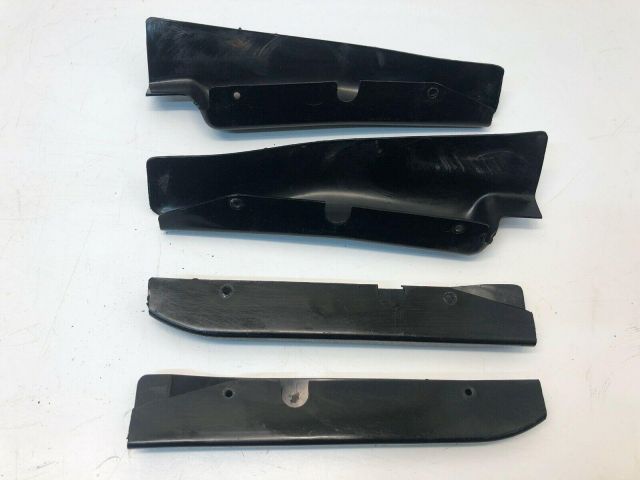
Thanks in advance for any help!
Nick
-
So having put the dash back together just now I started the car to make sure everything was still working and noticed that the tachometer and the indicators were no longer working. The only thing that I could think that I had changed between them working yesterday morning and now not working was the frayed wire and the 25A fuse out for a 35A fuse
So I just put the 25A fuse back in and they are all working again. I know, Rob, you said that a 35A fuse was correct so do you think that this is/will be an issue?
Thanks again, Nick
-
Hi Rob
Thanks again.
Have tested the fuse connections and they were the correct way round. I've reconnected a new wire in place of the old one so hopefully all good now! The fuse was also a 25A fuse so I've replaced that with 35A fuse too.
Have checked the radio cable and you are correct, with the keys at the accessories position it goes live.
Thanks again
Nick
-
Hi Rob
Thanks again for replying and being so helpful!!
When you say that it should be connected to the downstream end of the fuse, how can I tell which end is which? I will see if I can either put it in circuit or put a bulb in.
Yes that's what I thought I was reading on the 1500 wiring diagram but wanted to make sure I was reading it properly! Thanks for confirming.
Ahh white and faded brown would make sense, there is a radio in the car but totally disconnected. I have been wandering about maybe getting it reconnected so good to know, will check it like you suggest! As an aside to do with that do you know if there was a standard placement of speakers for Spits fitted with radios? I know I'm unlikely to hear anything whilst driving and actually the engine and pipes are a good enough radio by themselves but seeing as it has one it'd be nice to make it work haha!
Thanks again for all your help!
Nick
-
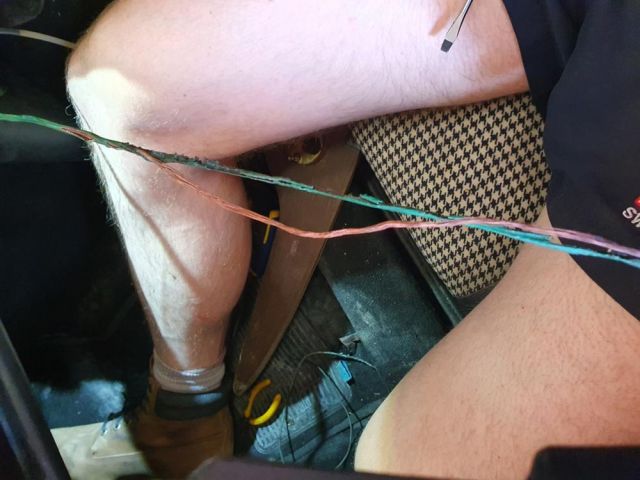
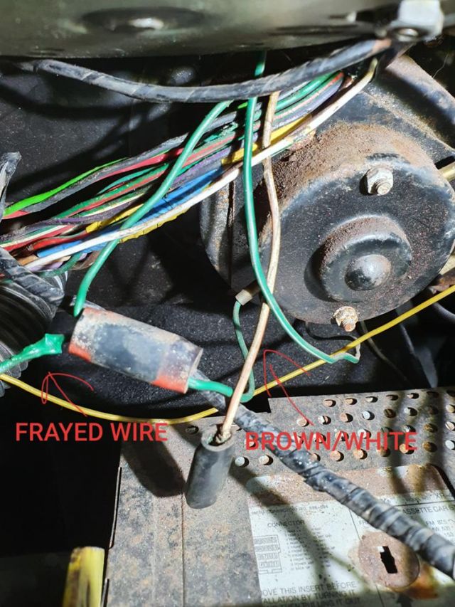
Hi all
So I noticed that one of the green wires coming from the top fuse in my Spitfire had a melted cover and bare exposed wires (NOT GOOD!). Having traced it I've found that it connects to a double bullet connector and then that goes to the heater motor (which I've realised is off a 1500). Photos as below. I have also discovered an unconnected Brown/White wire which I am slightly confused as to the purpose of and whether it ought to be connected!?
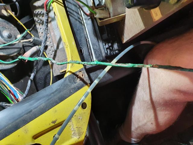
So, I have a couple of questions;
1. I'm assuming the damage to the melted green cable is due to overheating!? But not sure why it would have happened, all the other wires in the harness look fine, just this one that is melted and frayed. Looking at the wiring diagram (for a RHD 1500) I think it is correct that it goes to the fuse box.
2. Does anyone have an idea what that White/Brown cable is for? I think from looking at the Mk4 and 1500 wiring diagram it looks like it should be the Oil Pressure warning light? Forgive me if this is a stupid question but is that not the green light on the speedo that says OIL?
Thanks in advance.
Nick
-
Thanks Rob, I will check the LH bulb for an earth and the number plate lights too. Although there is only the one cable from each of the bulbs, through the rear panel that then goes to a double bullet connector and then connects to the LH rear lamp, so would the earth be the same as for the LH bulb, essentially same fault for both issues, LH rear lamp is not earthed?
Yes, I had looked at Haynes and Owners' Manual wiring diagrams and could not see a GY wire from the brake switch hence the confusion haha! Strange, perhaps a PO has installed a LHD loom for some reason! The connector on the brake switch does have both the Green cables attached (one shares a terminal with the GY wire) so that is clearly why they work without it being attached! I will double check to make sure my reverse lights are working though!!
Thanks again. Nick
-
Hi all
Been doing a bit of work on my Mk4 Spitfire recently. One of the jobs that needed doing was to fit a wire from the right hand number plate light to the connection that goes to the rear lights. So I did that earlier. When I went to test it neither number plate light now works...despite the left hand one previously working. The bulbs are both fine. So my first question is does anyone have any idea as to why this might be? The rear lights are still working when I turn the lights on but neither number plate lamp now works.
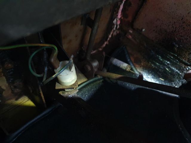
Also I noticed a yellow/green wire dangling from under the dashboard. Having had to work under there recently to fix my ignition lamp I judged that I must have knocked it and not realised. I traced it to the brake light switch on the brake pedal (see below photo) but can't work out where the loose end is meant to connect to, it has a female spade connector on the loose end. When I have tested the brake lights by depressing the pedal they both come on even with this cable disconnected. Also, strangely, if I turn the rear lights on and then press the brake light the right hand brake light illuminates but the left hand light turns off and the left hand brake light does not illuminate...!?
Hope someone is able to help! Thanks in advance!
Nick
-
Hi all
Been doing a bit of work on my Mk4 Spitfire recently. One of the jobs that needed doing was to fit a wire from the right hand number plate light to the connection that goes to the rear lights. So I did that earlier. When I went to test it neither number plate light now works...despite the left hand one previously working. The bulbs are both fine. So my first question is does anyone have any idea as to why this might be? The rear lights are still working when I turn the lights on but neither number plate lamp now works.
Also I noticed a yellow/green wire dangling from under the dashboard. Having had to work under there recently to fix my ignition lamp I judged that I must have knocked it and not realised. I traced it to the brake light switch on the brake pedal (see below photo) but can't work out where the loose end is meant to connect to, it has a female spade connector on the loose end. When I have tested the brake lights by depressing the pedal they both come on even with this cable disconnected. Also, strangely, if I turn the rear lights on and then press the brake light the right hand brake light illuminates but the left hand light turns off and the left hand brake light does not illuminate...!?
Hope someone is able to help! Thanks in advance!
Nick
-
Thanks Rob. Maybe I won't bother with LEDs then, atleast for now anyway!
I've managed to reconnect the bulb holder and can now report that the alternator is finally working properly again! So thanks to everyone for the help, I would never even have thought that that could have been the problem!
Next job trying to reconnect the tachometer (amongst some other, more cosmetic jobs!)
-
Hi Clive, thanks for the reply
Roger that re LEDs. Would you say the same for headlights etc. or would these be worth 'upgrading'?
For the tachometer earth is that just a short cable from the tacho to the speedo nut then?
Yep, the bullet connector is the only one that actually has a wire and is connected in my car and it does go to the coil. For the dark green wire to the voltage stabiliser, do you know what amp wire should be used for this?
Unfortunately the Haynes and the Owners Workshop Manual don't mention wire gauges/amps anywhere (just colours) and there is of-course a wide selection of wires at different ratings available! I have tried googling but can't find a definitive answer, was rather hoping that somewhere out there there might be a list of what gauge wires are necessary for each connection in the loom!
Cheers, Nick


How to find private workshops for sale?
in Triumph Chat
Posted
The issue is though, the houses we can afford in the areas we are looking won't have the space to do this...! Hence trying to look at possibility of buying or renting workshop/domestic garage space elsewhere.